
BLOCKsignalling BOD2-NS Bod2 NS Train Detector (IR) No Soldering
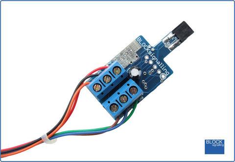
BLOCKsignalling Infra-Red Triggered Block Occupancy Detector (BOD2-NS) No soldering required. Quick and easy way to detect trains anywhere on your layout, even in tunnels Detects passing trains using its in-built infra-red sensor Operates from 8V to 25V DC, 8V to 16V AC, or uses DCC as a power feed and feeds signals at 12V Very easy to connect up to simple indications on a control panel or to add as inputs to computer systems No soldering required, all components are ready wired No programming necessary(but you can adjust all settings if you wish) We often are asked how to detect trains in tunnels, or on layouts where enthusiasts run their trains in twilight, or even in complete darkness. In these situations, photocell operated detectors will not work, and so you need a detector with a built-in light source. The BOD2-NS has a built-in infra-red detector which can "see" in the dark and can detect trains in these situations. Two leds and a small relay can be connected. Normally one of the leds is lit ("NO TRAIN"). When a train crosses the sensor, the first led is extinguished and the second led is lit (and relay, if connected) is energised. These leds can be fixed on a control panel to show a train has crossed the sensor. After the train clears the sensor, the module resets to just the first led being illuminated. A delay can be set before this occurs to allow the train indication to remain present for a period, or the indication can immediately reset to the first led being illuminated. The instantaneous mode is useful for precisely locating a train, for example for uncoupling, whereas the delayed mode gives a train present indication and ignores the gaps between the carriages. You can power the module from 12V-25V DC, 12V to 16V AC, or from a DCC bus feed. The module reduces the supply voltage down to 12V to feed the signals and external resistors are not required as these are built into the module. Installation Simply drill an 8mm hole through the baseboard between the sleepers and insert the sensor from below. Train Detector If required, the sensor can be held in place using a small amount of blutack, expanded polystyrene or similar. The led diameter is 2.2mm, so on smaller scales the leds can still have a clear view between the sleepers. Train Detector Power Supply The module will operate reliably with a power supply in the range of 12V to 25V DC, or 12V to 16V AC, or a DCC feed from the track for example. When connecting a DC supply, connect the negative to the GND terminal and the positive to the Vin terminal. If the connections are accidentally reversed, the module will not function, but no damage will result. When connecting AC or DCC, the connections can be made either way around. Led Connection When using leds it is important to connect them the right way around. The negative lead (cathode) is identified by a flat on the side of the led body, and by having a shorter lead. led anode and cathode connections Wiring the Module Dapol Signal Module The module has six terminals. Vin This is one side of the AC or DCC supply input feeding the module (or the positive feed if a DC supply is being used) GND This is the other side of the AC or DCC supply input feeding the module (or the negative feed if a DC supply is being used). It is also the signal common wire. Vout This is a regulated +12V DC output which can be used to feed connected leds and the relay. CH1 The terminal is grounded to activate the attached relay. CH2 The terminal is grounded to activate the attached led. This is the "TRAIN DETECTED" led. CH3 The terminal is grounded to activate the attached led. This is the "NO TRAIN" led. Resistors are built into the module for terminals CH2 and CH3, so no external resistors are necessary. If you already have resistors wired in to your leds, then they can be left in place if you wish, although the led brightness may be slightly diminished. Connecting a Relay A miniature relay can be connected to the CH1 terminal. It is important to use a 12V relay with a coil resistance of at least 400 ohms. Using a relay with lower resistance may cause damage to the module. It is not necessary to use a diode across the relay coil as one is built in to the module. Download full documentation from: www.blocksignalling.co.uk
BOD2-NS